

2026 Top Automated Tank Filling Solutions for Buyers
Choosing a tank filling system in 2026 is less about chasing maximum speed and more about matching equipment to the product, container, and workflow. Viscosity, foaming, temperature, and target fill volume all influence the right design. A water-like liquid may run smoothly through a gravity filler, while syrup or oil may need controlled pumping and slower nozzle action. Small details matter. Drip trays, hose routing, changeover time, and cleaning access can affect daily output as much as the filling head. An Automated Tank Filling Solution should be assessed as part of a complete line, not as a standalone machine. That distinction is easy to overlook.
This guide introduces leading solution types and practical selection criteria for buyers comparing manufacturers, integrators, and configurations. It considers expected throughput, tank geometry, level controls, metering accuracy, operator interfaces, and compatibility with upstream and downstream equipment. Buyers should request product trials, documented test conditions, service plans, and clear explanations of quoted accuracy. Numbers without context can mislead. Ask how the system behaves during startup, low tank levels, product changes, and brief interruptions. Compare installation needs, spare-part access, and training, not just purchase price. No system fits every plant. Even a well-specified filler may need adjustment after production begins. Treat vendor claims as starting points, then verify them against your containers, products, and shift patterns. This overview cannot replace a site assessment, but it can help buyers ask sharper questions before investing.
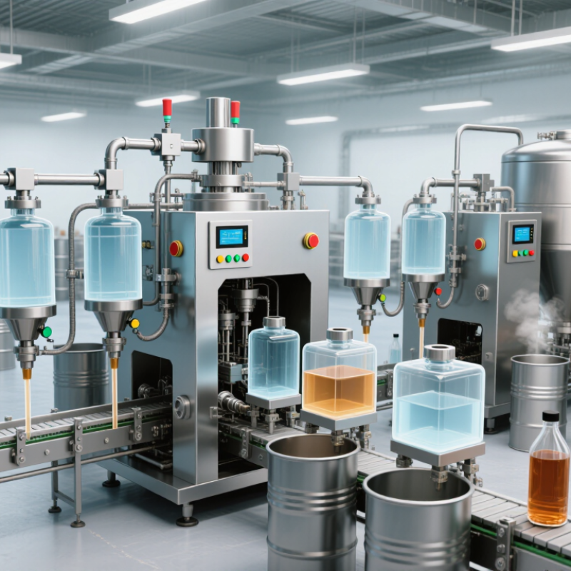
How Automated Tank Filling Systems Work
Automated tank filling systems coordinate a supply pump, control panel, flow meter, and filling valve. An operator selects a target volume or fill level. The controller checks that the tank is ready, then opens the valve and starts the pump. Sensors track the incoming liquid. When the target is reached, the valve closes and the pump stops. A drip tray catches small spills. Simple in principle.
Different systems measure filling in different ways. A flow meter counts liquid moving through the pipe, while a level sensor detects the rising surface inside the tank. The controller can pause filling if a sensor reports an unexpected level or flow. In practical installations, tank shape, liquid temperature, and foam can affect readings. A clean diagram may hide these small complications. They deserve attention during setup and routine checks.
Tips: Confirm sensor readings against a known volume before production. Keep probes and nozzles clean, and inspect seals for wear. Test the stop function with the tank partly filled, not only when empty. Record any drift between the system display and measured output. A little variation may be normal, but unexplained changes should prompt a closer inspection.
2026 Top Automated Tank Filling Solutions for Buyers - How Automated Tank Filling Systems Work
Compare common filling approaches by operating principle, suitable applications, and practical buying considerations. Performance figures are indicative; actual results depend on the liquid, equipment, installation, and calibration.
| Solution type | How automated filling works | Typical control basis | Best suited for | Key advantages | Buyer considerations |
|---|---|---|---|---|---|
| Load-cell gravimetric filling | Load cells weigh the tank or vessel as product enters. A controller slows or stops the pump or valve when the target mass is reached. | Weight; suitable systems can commonly control batch mass to within roughly 0.1–0.5% under appropriate conditions. | Batching where mass is the required measure, including liquids whose density changes with temperature or formulation. | Measures product mass directly and does not rely on a fixed density-to-volume conversion. | Tank supports, pipe connections, vibration, and mechanical forces can affect readings. Check scale capacity, calibration, and installation design. |
| Coriolis mass-flow batching | A Coriolis meter measures mass flow in the filling line. The controller totals the measured flow and closes the valve or stops the pump at the batch target. | Mass flow; meter accuracy is often specified around ±0.1–0.2% of reading for suitable liquid applications, subject to model and conditions. | Higher-value batches, recipe dosing, and processes that need mass-flow measurement or additional fluid data. | Can measure mass without a separate density input and can provide repeatable batch totals. | Evaluate purchase cost, line size, pressure drop, flow range, entrained gas, and compatibility with the liquid and cleaning process. |
| Magnetic flowmeter filling | A magnetic flowmeter measures the volume of conductive liquid moving through a full pipe. A batch controller stops flow when the preset volume is reached. | Volumetric flow; accuracy commonly falls around ±0.2–0.5% of reading for appropriately selected and installed meters. | Conductive liquids in full-pipe systems, such as many water-based products and process fluids. | No moving parts in the flow path; useful for continuous measurement and batch control. | Not suitable for non-conductive liquids such as many oils. Confirm minimum conductivity, grounding, pipe-full conditions, and liner compatibility. |
| Positive-displacement meter filling | The meter counts fixed volumes as liquid passes through it. A preset counter or controller stops the filling cycle at the selected total. | Volumetric total; performance depends on meter design, fluid properties, operating range, and calibration. | Many clean, compatible liquids, including some viscous products and applications with steady, measurable flow. | Measures volume directly and can work with liquids that are unsuitable for magnetic meters. | Check viscosity range, solids, wear, pressure drop, seal materials, and maintenance needs. Meter performance can vary with flow and fluid conditions. |
| Level-sensor-controlled filling | A level instrument measures liquid height or level in the tank. A PLC starts, modulates, or stops the inlet valve or pump at configured setpoints. | Tank level; volume accuracy depends on tank geometry, sensor technology, installation, and calibration. | Maintaining tank inventory, high/low-level control, and preventing overflow or dry running. | Supports continuous tank management and can provide independent high-level alarms. | Level is not always a precise batch measure. Consider foam, vapor, agitation, tank shape, sensor access, and independent overfill protection. |
| Timed pump or valve filling | A controller runs a pump or opens a valve for a preset duration. The target quantity is estimated from a previously established flow rate. | Elapsed time and estimated flow; no direct measurement of each batch quantity. | Simple, low-cost transfer tasks where quantity tolerance is broad and operating conditions remain stable. | Simple controls and relatively low instrumentation requirements. | Flow changes with pressure, temperature, viscosity, and equipment wear, so this method is generally less repeatable than measured batching. |
Selection note: Confirm the target quantity (mass, volume, or level), required repeatability, flow range, liquid properties, wetted-material compatibility, cleaning method, safety requirements, and integration with the plant control system before specifying equipment.