How to Choose the Right Control Valve for Your System?
Choosing the right Control Valve is a practical engineering decision, not a catalog exercise. It affects flow stability, energy use, equipment protection, and plant safety. A valve that looks suitable on paper may behave poorly when temperature, viscosity, or pressure changes.
Béla G. Lipták, a respected control engineering author, wrote, “The control valve is the most common final control element in process control.” That observation remains important in modern systems. The valve receives the controller’s signal, then physically changes the process. Small sizing mistakes can create hunting, excessive noise, cavitation, or weak controllability. The sound may resemble a harsh whistle near the pipeline. That detail often reveals trouble before an instrument alarm appears.
This guide examines how to choose a Control Valve for real operating conditions. It considers fluid characteristics, flow range, pressure drop, valve authority, body materials, actuator selection, and failure position. It also considers maintenance access, spare parts, and applicable industry standards. Those details matter after commissioning, not only during design review.
No selection method is perfect. Real plants expose assumptions. A valve sized for normal flow may struggle during startup or turndown. A cheaper actuator may also increase maintenance costs later. Engineers should verify calculations with process data, manufacturer performance curves, and field experience. Independent review can reveal overlooked risks, especially where fluids are corrosive, abrasive, toxic, or highly volatile. The aim is not to find the largest or most advanced valve. It is to find a reliable match between process behavior, control objectives, and long-term operating reality.
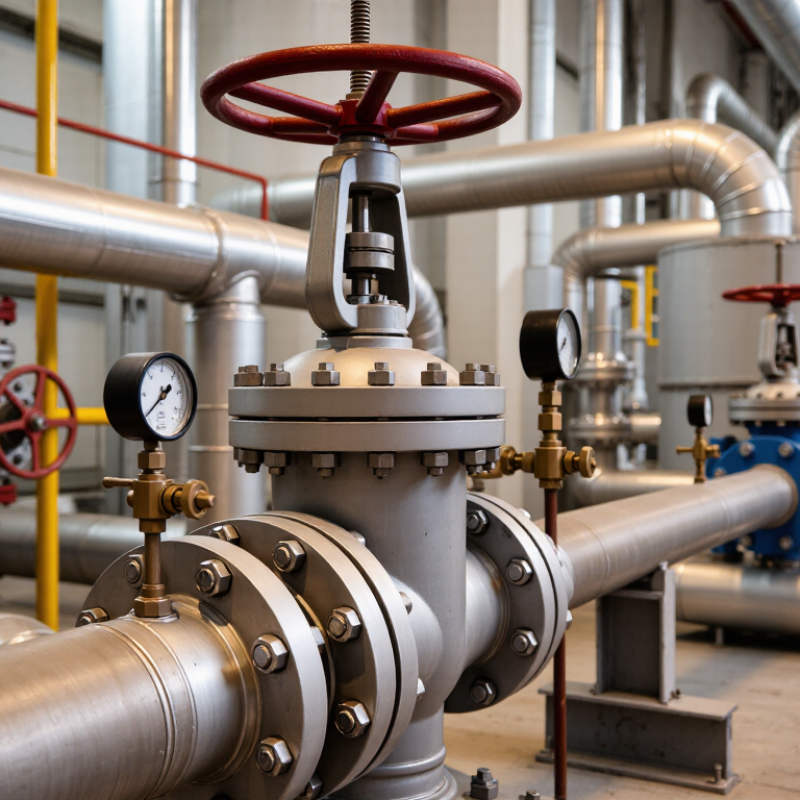
Define the Control Task and Process Requirements
How to Choose the Right Control Valve for Your System?
Define the Control Task and Process Requirements
Start with the process. A control valve should solve a specific operating problem, not simply match a pipe size. Decide whether it must regulate flow, pressure, temperature, level, or a combination of these variables. Define the normal, minimum, and maximum flow rates. Record inlet and outlet pressure, temperature, fluid density, viscosity, and any suspended particles.
Small details matter. A liquid may flash when pressure drops too quickly. A gas may create excessive noise at high velocity. Corrosive or abrasive media can shorten service life and damage internal parts. Calculate the required pressure drop under real operating conditions. Avoid sizing the valve only for normal flow. That approach may leave insufficient control during startup or peak demand.
Specify the desired failure position before selecting the actuator. Consider whether the valve should close, open, or hold position after power or signal loss. Match the response speed to the process. A fast actuator may cause pressure surges, while a slow one may produce unstable control. I have seen technically correct selections fail because actual site conditions differed from the design sheet. Verify measurements with operators and inspect the installation area. Check available space, ambient temperature, signal type, maintenance access, and applicable engineering standards. A documented calculation, reviewed by a qualified engineer, makes the decision more reliable. Still, some assumptions deserve a second review.
How to Choose the Right Control Valve for Your System? — Define the Control Task and Process Requirements
Start with the minimum, normal, and maximum operating cases. The control valve should provide stable regulation across the required flow range while handling the available pressure drop and process temperature.
Selection focus: The valve must control approximately 10–75 m³/h, operate with a pressure drop of 0.5–1.8 bar, and withstand process temperatures from 70–130°C. These requirements help determine valve size, trim characteristics, materials, and actuator capacity.
Match Valve Design to Fluid and Operating Conditions
How to Choose the Right Control Valve for Your System?
Match Valve Design to Fluid and Operating Conditions
A control valve should fit the fluid before it fits the pipe. Water, steam, air, and chemical liquids behave differently under pressure. Identify the normal, minimum, and maximum flow rates before selecting valve size. Oversizing often causes unstable control, even when the valve appears technically adequate. Small opening changes can then create sudden flow increases. That is risky.
Fluid condition also determines the valve design. Globe valves provide accurate throttling for many clean liquid and gas services. Ball valves can handle high flow with relatively low pressure loss. Butterfly valves may suit larger pipelines, but their control range requires careful checking. Liquids containing particles need erosion-resistant internal parts and suitable clearances. Corrosive fluids demand compatible body and trim materials. Material charts alone may not reflect real operating mixtures.
Pressure and temperature deserve equal attention. Check for cavitation in liquids and flashing near pressure drops. For steam and gas, calculate noise, velocity, and possible choking conditions. An experienced engineer will also review actuator force, fail position, leakage class, and maintenance access. I have seen specifications focus on flow capacity while ignoring installation orientation. That mistake can complicate inspection and future repairs. Use verified process data, not estimates copied from an old drawing. Recheck the selection at startup, normal load, and upset conditions. A valve that works on paper may still respond poorly in the field.
Compare Actuation, Control, and Safety Features
When selecting a control valve, compare the actuator, control method, and safety behavior as one system. I have inspected valves that matched the process size but reacted too slowly during load changes. The actuator determines response, available force, and maintenance needs. Pneumatic actuators suit fast, frequent modulation when air supply is dependable. Electric actuators simplify utilities but may respond more slowly. Hydraulic units provide high force, yet their power systems require careful upkeep. Check travel time, thrust margin, duty cycle, and failure behavior before choosing.
Control performance depends on more than valve size. Match the valve characteristic to the process gain and operating range. Confirm required Cv, rangeability, hysteresis, deadband, and expected pressure drop. Response matters. A positioner can improve accuracy, but it cannot correct poor sizing. On-off service needs reliable end-position feedback. Modulating service needs stable signal resolution and repeatable travel. I once focused too heavily on maximum flow. That decision was too narrow. Minimum controllable flow mattered more.
Safety features should be tested under realistic failure conditions. Decide whether the valve must fail open, fail closed, or remain in place. Consider loss of air, power, signal, and communication separately. Add local indication, manual override controls, and verifiable position feedback where operators need them. For critical isolation, assess partial-stroke testing, response time, and independent shutdown logic. Use documented calculations and applicable process safety standards. Ask how the valve behaves with low temperatures, dirty fluids, or blocked exhaust. Field conditions differ. Leave room for uncertainty, because assumptions often fail during commissioning.